Description
⚡ Elevate your signal game — isolate, stabilize, dominate!
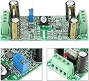
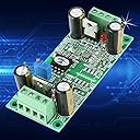
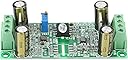
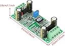
- COMPACT DURABLE DESIGN - Small footprint (3.3x1.4x1.1 inches) fits seamlessly into metal enclosures for enhanced grounding and EMI protection.
- FINE TUNE OUTPUT VOLTAGE - Built-in potentiometer allows precise calibration of output voltage to perfectly match your control requirements.
- DUAL INDEPENDENT POWER INPUTS - Supports two fully isolated 12-32V DC power supplies to maximize noise rejection and system safety.
- PRECISION ISOLATION FOR STABILITY - Ensures clean 0-10V analog signal transfer with ±3% accuracy, eliminating interference for your PLC/MCU systems.
- PLUG AND PLAY INDUSTRIAL COMPATIBILITY - Ideal for isolating high voltage or noisy signals in industrial automation, CNC spindle control, and advanced PLC setups.
The S-10V10V Signal Isolation Module is a compact, high-performance device designed to isolate and stabilize 0-10V analog voltage signals for PLCs and MCUs. Operating on dual independent 12-32V DC power supplies, it delivers fast 200ms conversion with ±3% accuracy, ensuring interference-free signal transmission in industrial environments. Its adjustable output and metal enclosure compatibility make it a must-have for professionals seeking reliable, noise-resistant control systems.