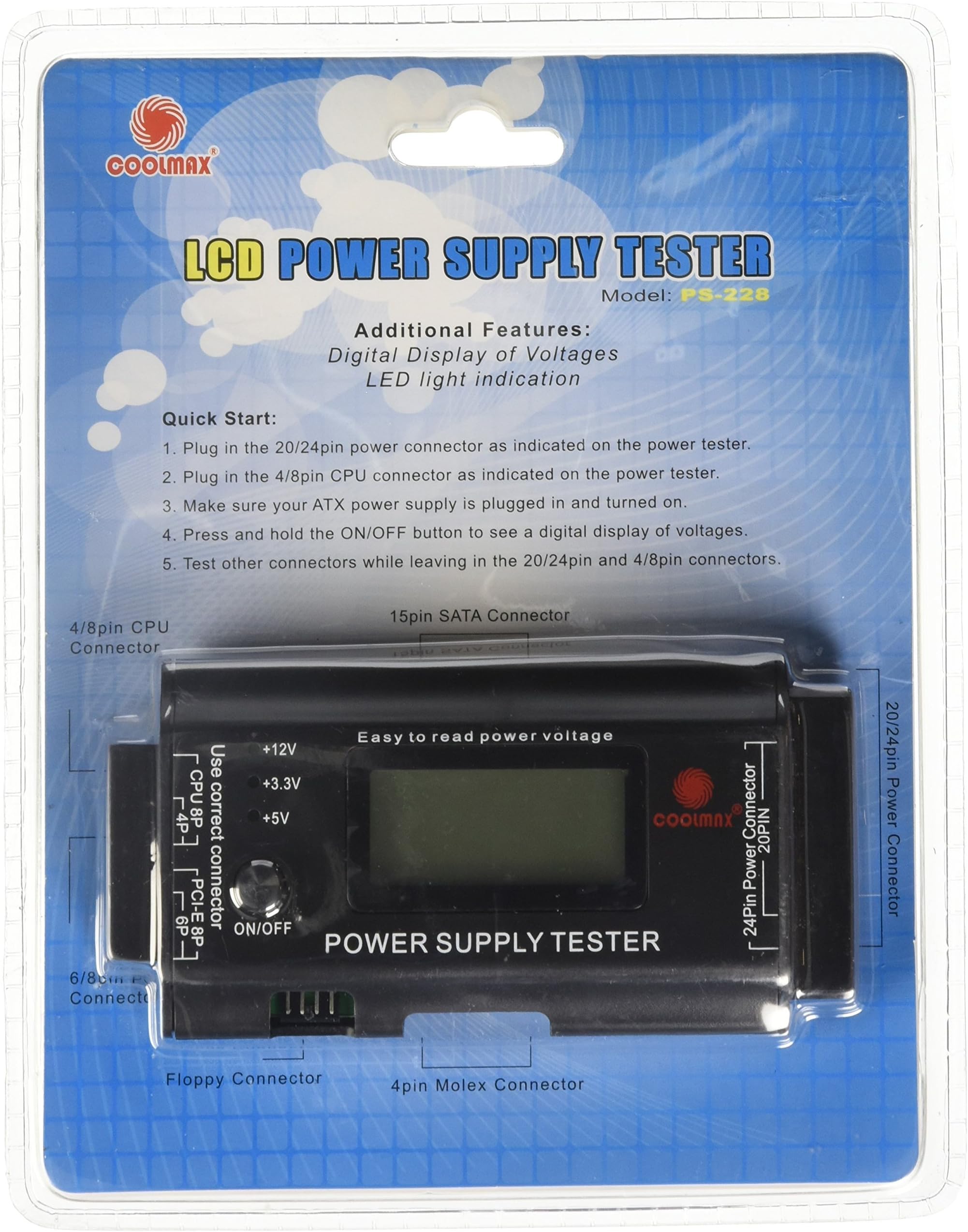

Coolmax LCD Power Supply Tester PS-228
Product ID: 2855239
⚡Accurate Readings ±0.1V
📊Large LCD Display
🔌8-pin PCIe Connector
🔧 Power Up Your Diagnostics with Precision!
The LCD Power Supply Tester PS-228 is a cutting-edge tool designed for PC enthusiasts and professionals alike. It features a large, backlit LCD display for clear readings, compatibility with both 20-pin and 24-pin power supply units, and introduces an 8-pin PCI-Express connector. With its ability to provide accurate voltage readings up to ±0.1V, this tester is the ultimate solution for diagnosing and troubleshooting power supply issues efficiently.
| ASIN | B002R06PGE |
| Best Sellers Rank | #11,491 in Computer Power Supplies |
| Brand | COOLMAX |
| Brand Name | COOLMAX |
| Compatible Devices | Personal Computer |
| Customer Reviews | 4.1 out of 5 stars 115 Reviews |
| Global Trade Identification Number | 00132018316849 |
| Item Dimensions | 2.76 x 2.36 x 0.39 inches |
| Item Weight | 4 ounces |
| Item dimensions L x W x H | 2.76 x 2.36 x 0.39 inches |
| Manufacturer | CoolMax USA |
| Model | PS-228 |
| Part Number | PS-228 |
| Power Source | Battery Powered |
| UPC | 191120085449 895963149121 172302774740 918510770071 132018316849 |
G**E
Works well - valuable troubleshooting tool
I purchased this because I was having some strange computer problems and suspected the power supply. I got this one through Amazon.com because it was half the price of the identical unit at the local branch of a major computer parts chain. I won't go into operation and use of the unit because other reviewers (especially P.S. and R.W.) have already provided great detail. If you are troubleshooting a modern desktop computer power supply (ATX style) or an older AT style, you must have one of these. It is about as easy as it can get to operate: connect the motherboard and CPU power plugs to the tool, and disk drive and SATA power plugs if you want to test power for those as well. Then press and hold the button and read the display. One thing that is rarely mentioned is that the power supply must have correct load impedances attached before it can operate at all. That is a characteristic of all switching power supplies, not just these. A switching power supply is not like an older analog power supply. If you disconnect it from the motherboard and try to measure output voltages, the power supply probably will not be operating. This tester provides the correct loads and makes the measurements for you. Another set of measurements it makes are critical time intervals during start-up, and the regular "power OK" signal that has timing and level requirements. Without this tool, you would also need an oscilloscope for those measurements. I have not had any physical problems such as those shown in user photos (end caps coming off, for example.) The only complaint I gave is the labeling. The case is black plastic, and all of the legends and markings are just raised black-on-black lettering. (User photos here show white lettering, but mine looks like the primary product photo - just all black.) It makes things hard to read, especially for eyes that are more than six decades old. I know there are ways to make the letters more visible, but a brighter light was more convenient. I highly recommend this if you are working on desktop computer equipment.
A**N
Great for testing power supplies - even ones that appear "OK"
This is wonderful for an instantaneous test of power supplies, to know if there is high or low voltage or a completely bad one. I work in a computer shop and have used this no less than 100 times for testing power supplies. There are a few cons of this product however to be aware of. 1. There isn't much documentation for instance it gives you a PG level, but no where does it tell you what this is. 2. The ends of the unit come off fairly easy where the plastic clips into the metal casing. It connects and tests 20/24 pin Motherboard connectors, 4 pin, and 8 pin EPS CPU connectors. SATA, Molex, and floppy connections, PCI-E 6 & 8 Pin connections. Good product overall with just the minor issues noted above. Would recommend to others.
A**T
Needs instructions, but it does the job
On the plus side, it works and gives you a good idea if your power supply is operating correctly or not. On the negative side, it beeps like a banshee if any of the voltages are out-of-whack. The beeping would be appropriate if this were a continuous tester, meant to be left in place while the system was in operation. In that case then, if a value went out of the normal range, then the beeping would be a plus. But for an intermediate tester like this one, where you're only going to be using it for a few minutes, the beeping is unbelievably annoying. (On that note: My dog thought it was the smoke alarm and totally freaked out over the sound.) Also, the instructions need help, but for that, see the rest of my review: INSTRUCTIONS: 1. First plug in the 20/24 pin motherboard power connector. 2. Hold the on button on the tester. All values except for +12V2 should be within their normal ranges (except possibly PG, see the end for details). 3. Don't unplug the 20/24 pin connector until you've tested everything else. 4. For each additional motherboard (4p/8p) or PCIE (6p/8p) connector, plug them in one at a time. When you hold the on button, the +12V2 should be in the normal range. Unplug each connector after you test it. 5. For each additional accessory (IDE/SATA/floppy) connector, plug them in one at a time. When you hold the on button, the +5 and +12 LEDs should light up. For most power supplies, the +3.3V LED should also light up for the SATA connector. Unplug each connector after you test it. NOTES: -All of the connectors with a clip (the 4, 6, 8, 20, and 24 pin connectors), plug in with the clip facing up. -The PG stands for "power good". This is the gray wire in the 20/24 pin connector. The power supply is supposed to do periodic self-tests and if everything is okay, then supply +5V along this wire. Some power supplies wire this directly to the +5V bus without doing the self-test. The tester detects this and will beep like crazy because of it. I have two known-good, high quality, name brand power supplies that "fail" for exactly this reason. -The SATA power connectors are supposed to supply +3.3V. However, in the early days of SATA, many people used IDE->SATA power adapters, but since the IDE power connector doesn't have +3.3V, neither did their SATA connector. As a result, very few devices actually use the +3.3V power and as a result, some power supplies might not supply +3.3V on the SATA connector (although they should). The point is that if you only get the +5V and +12V LEDs when you test your SATA cable, it's probably not a problem. -If the tester detects a very high or very low voltage, then it will flash "HH" or "LL". NORMAL RANGES (from the Coolmax website): Normal Voltage range Display Voltage range Line Ideal Lower (A) Higher (B) Min. (C) Max. (D) +5V 5.0V +4.75V +5.25V 4.0V 6.0V -12V -12V -11V -13V -10V -14V +12V1 12V 11V +13V 10V 14V +12V2 12V 11V +13V 10V 14V +3.3V 3.3V +3.14V +3.47V 2.0V 4.5V +5VSB 5V +4.75V +5.25V 4.0V 6.0V PG 0ms 990ms Unfortunately the tabulation isn't working right, but you should be able to work it out or find the original on Coolmax's website. So, for example, if you have 11.3V on the +12V2 line, then that is normal. If you have 10.5V, it is low and the tester will display "10.5". If you have 9.7V, it is low and the tester will display "LL".
S**)
Works Great
I have used this to test 5 different power supplies on my bench. 2 supplies are new, and 3 are bad. It identified the bad supplies instantly. It measures to 1/10th of a volt on all voltages, and was right on the money when compared to my Fluke Multimeter. It does not do a load test, but at least by checking the voltages to spec you protect your expensive mother board and peripherals from damage. The connection directions almost hit you in the face, as they are printed on a card that is readable through the clear retail bubble packaging. Very satisfied that I can now test my power supply voltages significantly faster.
Z**Y
cheap tester comes apart too easily
This unit will test your PSU and all the connectors; the LCD display shows voltages on all the rails nice and bright, and unit has interfaces for every type of connector. Drawbacks: none of the connectors are marked for how to connect(24 pin and 4/6/8 PSU pin, SATA) so it's a guess at first. the 24 and 4/6/8 connectors are keyed so there's only one way, but the SATA connector is neither marked or keyed so it's possible to install the PSU connectors backwards. A minor issue once you figure it out. My big gripe is that the 24 pin PSU connector is a tight fit, and trying to remove it causes the plastic panels on the other end of the unit to pop off as the unit is being pulled through it's outer case. This problem occurs when trying to remove the 4/6/8 pin connectors on the other side as well. I am concerned that one of these times it will possibly break/damage contacts with the on/off or LCD display. 3 of the PSU's I tested showed good results. a 4th one I tested was from a good, running PC, but the tester alarmed that +5V was too low (would show +5V for 2 seconds then drop off to 4.9, 4.8 then ""LL"). Keeping the PSU connected and powered on, every time I pressed the 'on' button on the tester I'd get the same result (+5v ok for a few seconds then drop to "LL"), so I don't think that my +5V is really dropping. However, the PSU works fine in the computer it came from, so I will have to test the PSU with another tester to confirm if it is really having problems or if the Coolmax tester doesn't like this particular brand of PSU. I'm inclined to return the product because of the shoddy workmanship. Having a tester come apart when trying to remove connectors is not my idea of quality; damage to the unit may even present a safety risk to you and/or the PSU you are testing. Update: I re-installed the 'defective' PSU on my motherboard and tested with a meter - all my voltages were good. PSU manufacturer confirmed that PSU will drop voltage if no load is present. This tester almost caused me to replace a perfectly good PSU.
D**.
Pegged 4 for 4 in early tests
The device seems to work as expected. I tested it on four power supplies...one I knew was bad, one I suspected was bad, and two I knew (or expected) to be good. It nailed all 4...the two bad ones showed what was wrong and the two good ones passed just fine. Makes me a little more willing to trust it on future PSU's now. I received this in a package that looked like it'd been open and re-taped shut (with 3 different sizes of tape). However, I'll rate the vendor separately on that. Unit itself worked fine. Note: Keep the motherboard power and cpu power plugged in through all the other tests and you shouldn't have any issues.
P**E
This is the real version
When I first started looking for one of these, I simply searched for "Power supply tester" and chose any of the ones on the front page, which also had the most stars & reviews- go figure. I wasn't sure exactly what to look for then. According to what I found online, you had to connect the main plug first along with some 6-pin connector that wasn't available on the older power supply I was testing. So basically, it wouldn't work. I took it to my labs and asked the instructor for assistance and the first words from his mouth: "Oh, that's one of those China knockoffs." He then pulled one of these out of the cabinet, and connected only the main plug. Fortunately the power supply was still good. I took note of the brand / model and immediately came home and purchased one of these. And I'm sending that other junk back. Yes- this one is $20 more, but it's well worth it.
S**R
Good for price, poor quality control. Here's Instructions
Model PS-228 ATX Coolmaxusa Power Supply Tester 1. POOR Quality Control. The Tester I received had a bad pin in the Floppy connector. Wiggling it caused the +5V light to go on/off. It was NOT caused by a bad power supply cable plug. I took the tester apart, and re-soldered the jack's pins. (The person building it had clipped the lead wires so short that most of the solder was gone from 2 of the pins.) This tester is so cheap for what it's got in it that it wasn't worth the aggravation to send it back to Amazon and get a replacement.) 2. It comes with incredibly poor instructions. It meets my needs, once I discovered its limitations, and what pins/connectors did what to which displays. But- for the price, it can't be beat. The Model PS-228 ATX Power Supply Tester(PST) tests computers containing an "ATX" compliant style power supply. It has a black aluminum case with plastic end caps, with a blue-lit LCD screen. It has a stated voltage display accuracy of 0.1V. It includes visual and audible alarms that tell you when the voltage level is too low(LL), too high(HH) or if there is no voltage from your power supply at all(LL). There is no "mute" for the alarm, but normally, you only need the tester "on" for a short while. The alarm is hi-pitch, so if your hearing is shot, you may have a hard time hearing it anyway. It doesn't know if a cable/wire is actually connected or not. (so if you don't have a cpu connector plug attached, then it'll alarm anyway (so, for a missing "+12V2" connection on the left end, it will indicate a normal "LL"). This tester does NOT TEST -5VDC (white wire on the 20/24 pin connector). That voltage was used more on older computers; newer ones may not use it. Its use is now "optional" in the current ATX power supply specs. Just BE AWARE that it's not being tested. If your computer needs it, and it's bad, you could still have a bad PSU. - I notice that the cheaper Coolmax "LED indicator only" version does have an LED to show -5V status, but it doesn't show actual voltages.) - I viewed the Antec power supply tester advertisement, but it had no Op.Manual to download (even on the Antec site), and doesn't appear to do as much as the Coolmax Tester, and had a much higher price. It did not measure -5V either. The LCD display shows actual voltages from only 3 plugs: (on the two ends): 1) Motherboard main power connector: (20, 20+4, or 24 pin connector plug, on right end) * +12V1(rail #1), -12V , +5V, +5VSB(StandBy), +3.3V * Also shows P.G. time value on LCD. * This tester does NOT measure the lesser used -5V volt rail at all. (white wire) -5V may still be required on older computers. 2) Motherboard CPU connector: 4 or 8 pin plug, +12V2 (rail #2), on Left end * Only test one CPU or PCI plug in left end at a time, not both together. 3) PCI-E Graphics card power connector: 6 pin, 6+2, or 8 pin plug. Voltage tested: +12V2 (rail #2) on Left end * Only test one CPU or PCI plug in left end at a time, not both together. In addition, there are THREE LEDs that work with 1 (of 3 styles) cables plugged into the upper/lower sides of the tester. These simply show the presence of voltages in each connector for Pass/Fail (light on/off). The 3 connectors on the long-upper/lower sides of the tester are for: 1) Floppy Drive style (+12V, +5V) 2) CD/DVD/Hard-drives(Molex Style) (+12V, +5V) 3) SATA power cables. (+12V, +5V, +3.3V) (not all SATA power plugs include the Orange +3.3V wire, nor do all SATA devices need +3.3V) * Only ONE of the 3 connectors should be connected at a time for proper LED indication. * These 3 connectors will NOT indicate their actual voltage at the connector (on the LCD display), nor will they show LL or HH. They simply show the presence of a voltage by lighting the LED. * +12V=yellow wire, +5V=Red wire , +3.3V=Orange wire in the SATA plug * The connectors on the ends of the tester do not have to be attached to use the LED lights. o However, the main power connector would have to be connected to motherboard, or its PS_ON wire connected to black ground wire for the power supply to activate. o In other words: If your computer powers on ok, but you've got a drive that's not powering up and you just want to check the drives power connector, you can. (without messing with any other cables) Two LEDs will light up, (or 3 on SATA plug , if it has the 3.3V wire) if the voltages are present at the connector. PG Time indicator: The PWR_OK wire in the 20/24 pin connector is an output from the power supply to the motherboard. Not all motherboards are designed to use this signal. The PG "time" is an indication of how fast the power supply reaches its proper voltages at turn-on. Faster is better. "PWR_OK is a "Power Good (PG)" signal. When power supply is turned on, AFTER the power supply sees that the primary voltages (+12 VDC, +5VDC, and +3.3VDC) are above the under-voltage thresholds, it changes PWR_OK from zero to +5V. It remains at +5 unless a problem is encountered within the PSU, or it's turned off. The "Power Supply Tester" measures the delay from initial press of its "ON button", to when the "PG" signal is generated by the power supply. (Per the ATX design criteria, it appears the design maximum should be 500mS.) This is the time it takes for proper voltages to be applied to the circuits in the computer. (design specs are not always reflected in actual operating values, especially in LOW end products. This isn't usually a critical issue.). IF the motherboard uses this signal, it typically won't start the bootup process until it reads that all power is good. (It uses +5SB to provide the power to read the PG signal) If you know what your power supply "normally" reads for PG, then (theoretically) a slowing over months could indicate possible deterioration. (Often, components fail abruptly, with no prior indication they are failing). I would take other factors into account before deciding to replace a power supply ONLY because its PG was over 900. Example: I know of at least one computer that actually monitors the "PWR_OK output. If the "Power Good (PG)" signal was not received within a full two seconds of turn-on(per design), then the computer would turn the power supply back off. Also, if the PG signal were reset "low" by the power supply itself during operation (because a voltage had dropped too low), then the power supply would shut itself off. Some good reference links: - For more info on computer power supply connections and cable configurations, go to the excellent [...] site: [...] Heed warnings regarding some Dell power supplies that at first glance "appear" to be ATX compliant, but are wired differently, and putting an ATX power supply in that computer may smoke the computer. (uses the same size connectors) [...] [ The PC Guide | Systems and Components Reference Guide | Power | The Power Supply | Power Supply Functions and Signals ] - Intel ATX/ATX12V Power Supply Design Guide [...] - And, for more "ATX" info, Search Google for "developer_specs_ATX12V_1_3dg.pdf" ____________________________________ I'm including my own version of Operator Manual/Guide: Basic Instructions: If testing a PSU(power supply unit) already connected in a computer, Safety First, (yours, and your computers) 1. First unplug the AC power cord while you move cables: 2. unplug the 20, 20+4, or 24 pin connector from motherboard and plug it into the tester on the Right end, in the position as indicated on the power tester. * If the power supply has a "20 +4" pin connector, then the 4 pin connector is usually wrapped to the 20 pin connector wire bundle. (This 4 pin connector has Red, Yellow, Orange, and Black wires. It's simply a second set of wires from the same power rails as in the 20 pin connector. Its function is to allow more current to be sent to the motherboard, without overheating the "20-pin" connectors. The 4-pin connector does not need to be connected to check the power supply voltages.) * This connector provides the LCD readings for: * PG time value * +12V1(rail #1), -12V , +5V, +5VSB(StandBy), +3.3V * This tester does NOT measure the lesser used -5V volt rail at all. (white wire) -5V may still be required on some, and especially in older computers. 3. Look for a 4 or 8-pin CPU connector on the motherboard (yellow & Black wires only), and plug it into the Left end of the connector indicated on the power tester. (=+12V2 on LCD) * If the power supply is older, it may not have that connector. In that case, the un-plugged CPU connector should show a normal "LL" for the "+12V2" indication. * Only plug one CPU or the PCI-E connector in at a time.(both will show as the "+12V2" display reading.) * There may be two 4 pin connectors. The CPU connector one has two(4) yellow and two(4) black wires. DO NOT force them into the wrong connectors!! This 4 pin connector, and the one in step two are the same size, though they should be keyed differently and therefore not "easily" inserted into the wrong socket. 4. If you also have a 6 or 8 pin PCI-Express cable [plug connected to your graphics card, don't plug it into the tester yet (until you've finished testing and unplugged the CPU plug).. * You may not have a PCI-E plug. If you do, then it also has only yellow and black wires, and would connect to your graphics card. * WARNING: DO NOT confuse it with the CPU connector, it's wired differently!! * The connectors have square or rounded ends at each pins housing. These act as a KEY to help prevent you from plugging it into the wrong connector. HOWEVER, with these style connectors, if you push hard enough, you CAN plug a square peg into a rounded Hole!! Be sure that you don't. (it could be a bad thing) 5. The power supply should be connected to external load for more accurate and safer (for Pwr Supply) testing: Plug one of the peripheral cable connectors into a device (CD/DVD/Hard drive for example) to provide a proper load on the power supply. (The voltage readings will be more likely to be correct with an actual and proper load applied to the Power Supply.) * Some better power supplies require a load on BOTH the +5V and the +12V rails before they will power up. * The "Power Supply Tester" only has one load resistor internally used for the +5V rail in the 20/24 pin connector; (a 33 Ohm 5W Resistor). It's enough load to power up (most) supplies, but with no load on the other rails, it's not enough by itself to accurately test the other power supply voltages. For more accurate voltage results, leave one of your drives connected to a power supply cable while you test. This provides a load for +5V and +12V1 rails) A SATA device may also provide a load for the +3.3V supply, but note that not all SATA devices use +3.3V. * Some power supplies may be damaged if they are powered up with no load. - My Tests: With only the 20 pin connector attached to the PST: the 12V read +11.7V & -11.1V. - With a 4-pin molex drive plug connected to the testers lower side connector, it read the same voltages (meaning the side plugs of the tester provide very little load.) - With a 4-pin molex power connector plugged into a DVD drive, the voltages read +12.1V & -11.5V. A more accurate assessment. 6. Plug the AC power cord into the power supply, and if it has a switch on the power supply, turn it on. The PS is now in Standby mode. (The +5VSB should now be live, but won't show yet on the LCD display) * NOT ALL PSU's have a power switch on them. They are "LIVE", in standby, as soon as a live power cord is attached. 7. You may test it now. To turn on the power supply, Press and Hold the tester on/off button. Read the voltages and confirm they are ok. Release the button. * If you need to hold the button down while you check cables etc., then one way is to wrap a rubber band around the case and over the button. Increase the pressure on the button by placing an object under the rubber band over the button(cut off a plastic BIC pen cap). Be aware that some (cheaper built) supplies may be damaged when running with no load for longer than a few moments. (The PST provides a load ONLY for the+5V supply.) * None of the 3 LEDs should be lit with this test (since no.cable is connected to them yet.) 8. If you have a PCI-E cable, go back to step 4, unplug the CPU cable, and plug in the PCI-E cable (if the computer has one), and press the button to test for +12V2 at that connector. (this 2nd test mainly verifies the wiring now) 9. If you wish to test the peripheral connectors wiring, do it now. Leaving the end-cables attached (so you can use the on/off button to turn the supply on with, and so the alarm doesn't sound). Then connect only ONE plug to the testers upper or lower SIDE connectors at a time. When you hold the on/off button down, two or more LED's should light up to indicate the presence of the voltages in the attached plug. This is simply telling you that the wiring to that plug is good. Wiggle the connector and wires to test for poor connections. NOTE: These upper/lower connectors do NOT show their voltage on the LCD display. The LCD display power and data comes from the L/R End connectors.) - Floppy connector should show the +12V & +5V LED Lights (The +12V is from the +12V1 rail) - HardDrive/CD/DVD 4-pin molex connector should show the +12V & +5V LED Lights (This +12V comes from the +12V1 rail) - SATA connector should show the +12V, +3.3V and +5V LED Lights * Not all SATA connectors include the +3.3V Orange wire * The +12V is from the "+12V1" rail * The SATA Tester connector is not "keyed". You must look into the SATA plug to see which side the pins are on. They should go to the top as you plug it in. (The bottom of the testers SATA connector has no contacts, so if you get it wrong, it simply won't show any lights, flip the plug over.) Quoted from Coolmax info: "- No voltage detect, "LL" will display on the screen. - When detected Voltage is lower than Min. Value, "LL" will display on the screen. - When detected Voltage is higher than Max. Value, "HH" will display on the screen. - When detected voltage is lower than table value (A), will alarm. - When detected voltage is higher than table value (B), will alarm. - P.G. value detected lower 100ms or higher 900ms, P.G. value is abnormal and alarm. - When abnormal happened, it will alarm and relative digit blink on the screen." _______________________________________ Standard ATX Power Supply wire color codes: RED = +5V Orange = +3.3V Yellow = +12V Blue = -12V White = -5V (optional) Purple = +5V VSB Green = PS ON Shorting the Green wire to Black(gnd) turns the PSU on. Gray = Pwr OK (PG) - The GREEN(PS_ON) Wire should measure +5V if the PSU is receiving AC power, but has not yet received the PS_ON "low" signal via motherboard, after pressing the on button. (The computer is "off" (Standby). In other words, when the AC power plug is connected to the PSU, and the rear PSU power switch is turned on, but the front computer power switch has not yet been pressed. The Motherboard should now be receiving the +5V VSB voltage to power the digital on/off circuit. - When the ON button is pressed, the motherboard brings the PS ON connection low. The PSU then tries to start up, and checks the 3 prime voltages it's producing. If all are OK, the PSU generates the PWR_OK high signal. If any of the 3 are out of spec, then the PSU turns itself back off. (This could be due to an internal PSU problem, or to an external problem, such as shorted output.) - With the PSU in Standby: The GRAY(PWR_OK) wire will measure LOW (~0V), - With the PSU turned ON: The GRAY(PWR_OK) wire will measure HIGH (+5V), if the PSU found all voltages measuring within spec. ~end~
Trustpilot
1 month ago
2 months ago